Method to Solve the Machining Deformation of 8020 Aluminum Parts
In the realm of precision engineering and manufacturing, the challenge of machining deformation in aluminum alloys, particularly in 8020 aluminum, stands as a formidable obstacle. As manufacturers strive for ever greater precision and reliability in their products, understanding and addressing the factors contributing to deformation during machining becomes imperative.
This introduction serves as a gateway to a comprehensive methodology aimed at mitigating the deleterious effects of machining deformation in 8020 aluminum parts.
Methods to Reduce Machining Deformation of Aluminum
1. Reducing Internal Stress in Blanks
Both natural and artificial aging as well as vibration treatments can partially eliminate internal stress in blanks. Pre-machining is also an effective method. For larger blanks, due to their larger allowances, machining deformation is also significant. Pre-machining excess material from the blank, reducing the allowances for each part, not only reduces machining deformation in subsequent processes but also allows for the release of some internal stress after pre-machining and a period of time for natural aging.

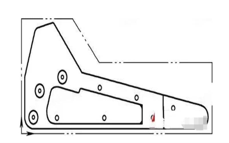
For example, in Figure 1, a beam component is shown where the blank, shaped as indicated by the dashed lines, weighs 60kg, while the component itself weighs only 3kg. Machining it in one step as shown by the dashed lines in the figure results in a flatness error of up to 14mm. However, if pre-machining is done as shown by the solid lines, followed by natural aging for a period before machining it into the desired component, the flatness error can be reduced to 3mm.
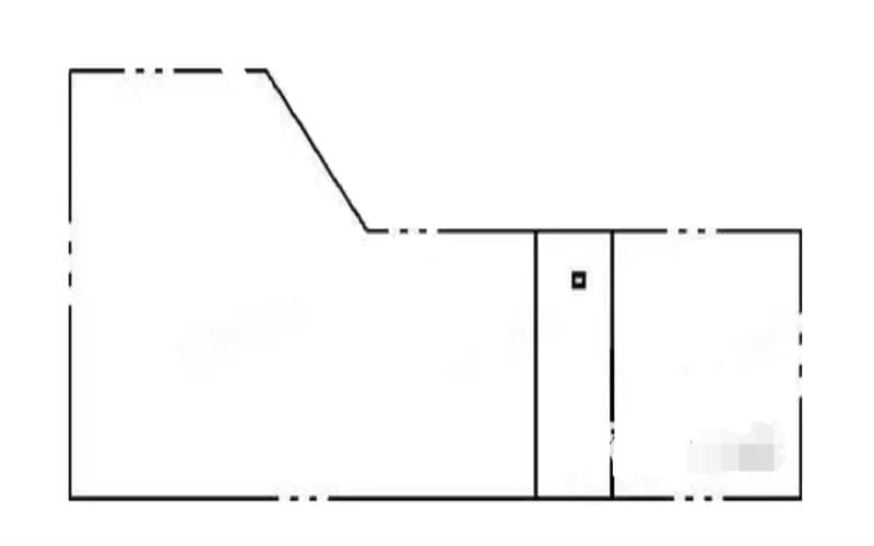
Figure 2 shows a certain type of cover part, where the local minimum thickness is only 3mm, and the thickness of the blank before machining is 20mm. It is possible to directly machine the part to size using a pressure plate on a machining center, but when removed from the worktable, the ends of the part’s bottom will lift up, resulting in severe dimensional deviations or even scrapping.
Therefore, before machining, create a stress relief groove on the blank, as shown by the solid lines in Figure 3, then remove it from the worktable, let it naturally age for 1 to 2 hours, allowing most of the deformation to occur during this time. Afterward, add a machining step to flatten the part, significantly reducing deformation during subsequent machining.
2. Improving Tool Cutting Performance
The material and geometric parameters of the tool have a significant impact on cutting forces and cutting heat. Correctly selecting the tool is crucial to reducing machining deformation in parts.
(1) Reasonably selecting tool geometric parameters:
- Rake angle: Choosing a larger rake angle can sharpen the cutting edge, reduce cutting deformation, ensure smooth chip evacuation, and thereby reduce cutting forces and temperatures.
- Relief angle: The relief angle affects wear on the tool’s trailing edge and the surface quality of the machined surface. The relief angle should be selected based on the cutting thickness. For rough milling, where the feed rate is high and the cutting load is heavy, a smaller relief angle should be chosen. For finishing milling, a larger relief angle should be chosen to ensure a sharp cutting edge, reduce friction between the trailing edge and the machined surface, and minimize elastic deformation.
- Helix angle: To ensure smooth milling and reduce milling forces, the helix angle should be as large as possible.
- Principal clearance angle: Properly reducing the principal clearance angle can improve heat dissipation conditions, reducing the average temperature in the cutting zone.
(2) Improving tool structure:
- Reduce the number of milling teeth and increase chip space. Due to the high plasticity of aluminum materials, machining deformation is significant, requiring a large chip space. Therefore, the bottom radius of the chip groove should be relatively large, and the number of milling teeth should be fewer.
- Precision grinding of teeth. The roughness value of the cutting edge of the tooth should be less than Ra=0.4um. Before using a new tool, it should be lightly ground with a fine oil stone in front and behind the tooth to eliminate burrs and slight sawtooth marks left during edge grinding. This not only reduces cutting heat but also minimizes cutting deformation.
- Strictly control the wear standards of the tool. After the tool wears, the roughness value of the workpiece surface increases, the cutting temperature rises, and the workpiece deformation increases. Therefore, in addition to selecting tools made of materials with good wear resistance, the wear standard of the tool should not exceed 0.2mm, otherwise, chip accumulation lumps may occur. During cutting, the temperature of the workpiece should generally not exceed 100°C to prevent deformation.
3. Improving Workpiece Clamping Methods
For workpieces with poor rigidity, such as thin-walled aluminum parts, the following clamping methods can be used to reduce deformation:
- For thin-walled bushing-type parts, if clamped radially using a three-jaw self-centering chuck or spring chuck, once loosened after machining, the workpiece will inevitably deform. In this case, it is best to use axial end-face clamping. Position the workpiece by the inner hole, make a threaded mandrel that fits into the workpiece’s inner hole, press the end face with a cover plate and tighten it with a nut. Machining the outer circle can then avoid clamping deformation and achieve satisfactory machining accuracy.
- When machining thin-walled plates or sheets, it is best to use vacuum suction cups to obtain evenly distributed clamping force and then use a smaller cutting amount to machine, which can effectively prevent workpiece deformation.
- Use the filling method. To increase the process rigidity of thin-walled workpieces, fill the interior of the workpiece with a medium to reduce deformation during clamping and cutting. For example, filling the workpiece with a urea melt containing 3% to 6% potassium nitrate, after machining, immerse the workpiece in water or alcohol to dissolve the filler and pour it out.
4. Properly Arranging Machining Processes
During high-speed cutting, due to the large machining allowance and intermittent cutting, vibration often occurs during milling, affecting machining accuracy and surface roughness. Therefore, the process of numerical control high-speed cutting can generally be divided into: roughing – semi-finishing – deburring – finishing and other processes. For parts with high precision requirements, sometimes secondary semi-finishing is required before finishing. After roughing, the workpiece can be allowed to cool naturally to eliminate internal stress generated during roughing and reduce deformation. The remaining allowance after roughing should be greater than the deformation amount, generally 1 to 2mm. During finishing, the workpiece’s finished surface should maintain a uniform machining allowance, generally 0.2 to 0.5mm, to keep the tool in a stable state during machining, greatly reducing cutting deformation, obtaining good surface machining quality, and ensuring product accuracy.
Avoiding Aluminum Deformation: Six Operational Methods
Apart from improving tool performance and adopting aging treatments to eliminate internal stress in materials, using appropriate operational methods can effectively avoid material machining deformation.
1. Symmetrical Machining Method
For parts with large machining allowances, to ensure good heat dissipation conditions during machining and avoid concentrated heat, symmetrical machining is advisable. For example, a block of material 90mm thick needs to be machined down to 60mm. If one side is milled first, and then the other side immediately afterward in one step, a flatness error of up to 5mm can occur. However, if the machining is done symmetrically, with each side machined to the final size in two steps, a flatness error of 0.3mm can be achieved.
2. Layered Multi-stage Machining Method
If there are multiple cavities on the sheet metal part, as shown in the figure below. When machining, it is not advisable to machine one cavity at a time, as this can cause uneven stress on the part and lead to deformation. Instead, a layered multi-stage machining approach can be adopted, where each layer is machined to all the cavities as much as possible simultaneously, followed by machining the next layer, ensuring even stress on the part and reducing deformation.
3. Properly Selecting Cutting Amounts
Reducing cutting forces and cutting heat by changing the cutting amounts. Among the three factors of cutting amounts, the depth of cut has a significant impact on cutting forces. If the machining allowance is too large and the cutting force per pass is too high, it not only causes workpiece deformation but also affects the rigidity of the machine tool spindle and reduces tool durability. By reducing the depth of cut and correspondingly increasing the feed rate and spindle speed while high-speed milling, cutting forces can be reduced while maintaining machining efficiency.
4. Proper Order of Tool Paths
Different tool path sequences should be used for roughing and finishing. Roughing emphasizes increasing machining efficiency and pursuing material removal rate per unit time, and reverse milling can be used. Finishing emphasizes high precision and high quality, and climb milling is appropriate. Climb milling gradually reduces the cutting thickness of the tooth from maximum to zero during cutting, reducing work hardening and minimizing workpiece deformation.
5. Secondary Clamping for Thin-walled Parts
For thin-walled parts, deformation during machining is difficult to avoid, even during finishing. To minimize workpiece deformation, the clamping device can be slightly loosened before the workpiece reaches its final size during finishing, allowing the workpiece to return to its original state, then re-tightened just enough to hold the workpiece, achieving the desired machining results. The point of clamping force should preferably be on the supporting surface, the clamping force should act in the direction of good workpiece rigidity, and the clamping force should be as small as possible while ensuring that the workpiece does not loosen.
6. Drill First Before Milling
When machining parts with cavities, it is not advisable to directly plunge the milling cutter into the workpiece like a drill, as this can lead to insufficient chip space for chip evacuation, causing poor chip evacuation, overheating, expansion of the workpiece, and tool failure. It is advisable to first use a drill with the same size or one size larger than the milling cutter to drill holes and then mill with the milling cutter. Alternatively, a spiral down-cut program can be generated using CAM software.
Conclusion
These methods, when implemented carefully and thoughtfully, can greatly reduce machining deformation of aluminum parts, ensuring higher precision and dimensional accuracy in the final products.For more information, visit Boyi website .

