Heat Dissipation Analysis of QSFP+ High-Speed Optical Module
Switches are a critical core component of information and communications technology (ICT) in data center infrastructure. With the parallel application of cloud computing, 5G, Internet of Things (IoT), and artificial intelligence (AI), the capacity and load required for computation and transaction processing of switches continue to grow exponentially, resulting in a rapid rise in power consumption. As the main heat source of the switch, the high-speed optical transceiver module will generate a lot of heat, which will significantly increase the junction temperature and limit the working performance of the switch. With the continuous improvement of the performance of the switch and the continuous increase of the assembly density, the heat flux density of the switch continues to increase. If a large amount of heat consumption in the switch cannot be dissipated in time, it will greatly affect the reliability of the switch. With the increase of packaging density, the heat flux density of the high-speed optical transceiver module increases rapidly. If reasonable heat dissipation measures are not taken, the internal temperature of the optical transceiver module will be too high, which may lead to bit errors, packet loss, and signal interruption in the optical transceiver module. and other problems, which will affect the stability of the data switch operation. In order to ensure the quality of data communication and the long-term normal use of the equipment, the heat dissipation analysis of the high-speed optical transceiver module must be carried out in the design process.
In this paper, thermal simulation analysis is used to verify and compare the design scheme, which has the advantages of low cost and high efficiency. In this paper, the 40G QSFP+ SR4 high-speed optical transceiver module is taken as the research object, and the temperature field of the high-speed optical transceiver module is simulated and analyzed with the help of thermal simulation analysis method, and the different heat dissipation optimization measures of the high-speed optical transceiver module are compared.
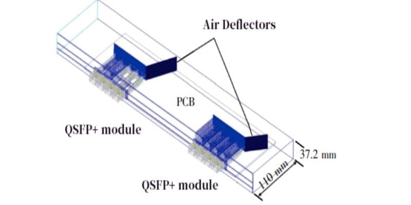
Add air deflectors
As shown in the figure below, the air deflector is added to the QSFP+ module, and the flow field distribution in the numerical wind tunnel is obtained. By adding an air guide plate and controlling the airflow direction, the heat dissipation of the optical transceiver module can be effectively improved.
Change the heatsink material
Based on the design of the radiator and air guide plate in the above figure, the radiator material is changed to copper (thermal conductivity 385 W/mK), and the analysis shows that the case temperature of the optical transceiver module is only reduced by 1 ℃.
Increase heat sink surface area
Increase the surface area of the heat sink, extend the heat sink to the rear of the optical module to the back side of the optical module (10 mm from the rear air duct wall), and add fins on both the upper and lower sides of the heat sink base plate, and design an air deflector. After simulation Analysis, the case temperature of the optical transceiver module dropped to 74.1 ℃.
Add heat pipe
In order to further improve the heat dissipation performance of the radiator, an ultra-thin heat pipe with a thickness of 1 mm is added to the radiator substrate, and the temperature cloud map of the module is obtained by simulation analysis. After optimization, the temperature difference of the radiator substrate is only 1.4 ℃, while the optical transceiver module The case temperature dropped to 71 °C.
Optimize duct size
The size of the air duct is reduced to 54.6 mm wide and 27.8 mm high. The size of the heat sink is kept the same. The copper heat sink is used to observe the flow field of the air duct. ℃ to 70.6 ℃.
Increase system air volume
Based on the air duct design, change the system air volume and design the system air volume to be 5, 7.5, 10 and 12.5 CFM respectively. It is concluded that when the system air volume increases to 12.5 CFM, the module case temperature drops to 68.4 ℃, which meets the requirement that the maximum case temperature of the optical transceiver module does not exceed 70 ℃.
Conclusion: comparison of improvement measures
After the optical transceiver module is improved by increasing the air guide plate, changing the radiator material, increasing the surface area of the radiator, increasing the heat pipe, optimizing the size of the air duct, increasing the air volume of the system and reducing the contact thermal resistance, the optical transceiver module is realized. The case temperature is controlled within 70 ℃. Among the above-mentioned optimization measures, increasing the air deflector to control the airflow direction and optimizing the size of the air duct is to increase the air volume on the surface of the radiator.
Through the above analysis, it is found that the air volume on the surface of the radiator and the contact thermal resistance between the radiator and the high-speed optical transceiver module have a greater impact on the case temperature of the optical transceiver module, which needs to be considered in the thermal design of the high-speed optical transceiver module.
